Change boundary conditions - Top3d
The boundary conditions are defined in an evolutionary way in our
top3dprogram. This tutorial will show you how to change boundary conditions effortlessly and effectively.
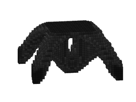
The boundary conditions and loading conditions are defined in lines 12-18. Since the node coordinates and node numbers are automatically mapped by the program, defining different boundary conditions is very simple. To solve a 3D wheel problem as shown below, which is constrained by planar joint on the corners with a downward point load in the center of the bottom, the following changes need to be made:

Step.1: Changing Loading Conditions
Step.2: Defining the Corresponding Boundary Conditions
Step.3: Run the program
The problem can be promoted by line:
Then, you should have result like this:
